Category Archives: Networks

Computer networks are a set of computer equipment and software connected to each other, with the purpose of sharing information, resources and provide services

Networks

Networks

Networks have become a fundamental part of today's information systems. They form the pillar in the sharing of information in companies as well as in government and scientific groups

This information can take different forms, be it as documents, data to be processed by another computer, files sent to colleagues, and even more exotic forms of data

History

Most of these networks were installed in the late 1960s and 1970s, when network design was regarded as the philosopher's stone of computer research and cutting-edge technology. It resulted in numerous network models such as packet switching technology, collision-sensing local area networks (LANs), hierarchical enterprise networks, and many other high-quality networks

Since the early 1970s, another aspect of networking technology has gained importance: the protocol stack model, which enables interoperability between applications. A whole range of architectures was proposed and implemented by various research teams and computer manufacturers

The result of all this practical knowledge is that today any group of users can find a physical network and architecture appropriate to their specific needs, from low-cost asynchronous lines, without any other error recovery method than a bitwise parity function, to full functions of wide area networks (WAN , public or private) with reliable protocols such as public packet switching networks or SNA private networks, up to local area networks, high speed but limited distance

The downside of this information explosion is the distressing situation that occurs when a group of users wants to extend their computer system to another group of users, which turns out to have different technology and network protocols. Consequently, even if they could agree on the type of network technology to physically connect their facilities, applications (such as mail systems) would still be unable to communicate with each other due to different protocols

He became aware of this situation quite early (in the early 1970s), thanks to a group of researchers in the United States, who were the architects of a new paradigm: networking. Other official organizations were involved in the interconnection of networks, such as ITU-T and ISO. They all tried to define a set of protocols, distributed in a well-defined set of layers, so that applications could communicate with each other, regardless of the underlying network technology and operating system on which each application was running

Internetworking

The original designers of the ARPANET protocol stack, subsidized by DARPA (Defense Advanced Research Projects Agency) introduced fundamental concepts such as layer structure and virtuality into the network world, well before ISO was interested

The official body of these researchers was the networked working group called ARPANET, which had its last general meeting in October 1971. DARPA has continued its research in search of a stack of network protocols, from the host-to-host NCP (Network Control Program) protocol to the TCP-IP protocol stack, which took the form it currently has from 1978

At the time, DARPA was an organism famous for pioneering packet switching over radio networks and satellite channels. The first actual implementation of the Internet occurred in 1980, when DARPA began converting machines from its working network (ARPANET) to the new TCP-IP protocols. In 1983 the transition was complete and DARPA demanded that all computers that wanted to connect to ARPANET use TCP-IP

DARPA also hired Bolt, Beranek, and Newman (BNN) to develop an implementation of the Berkeley UNIX TCP-IP protocols on VAX and provided the University of California, Berkeley to distribute that code free of charge with its UNIX operating system. The first release of the Berkeley system distribution that included the TCP-IP protocol was available in 1983 (BSD 4.2)

Since then, TCP-IP has spread rapidly among universities and research centres and has become the standard for UNIX-based communication subsystems. The second release (BSD 4.3) was distributed in 1986, which was updated in 1988 (BSD 4.3 Tahoe) and in 1990 (BSD 4.3 Reno). BSD 4.4 was distributed in 1993. Due to funding constraints, BSD 4.4 will be the latest distribution to be made by the Computer Systems Research Group at the University of California, Berkeley

As TCP-IP spread rapidly, new WANs were created and joined arpaNET in the United States. On the other hand, networks of other types, not necessarily based on TCP-IP, were added to the set of interconnected networks. The result was what is now known as the Internet

Internet

The word Internet is simply a contraction of the phrase interconnected network. However, capitalized refers to a global set of interconnected networks, so that the Internet is an interconnected network, but not the other way around. The Internet is sometimes called Connected Internet

The Internet consists of the following groups of networks:

  • Stem
    Large networks that exist mainly to interconnect other networks. Currently the trunk networks are NSFNET in the US, EBONE in Europe and the large commercial trunk networks
    Regional networks that connect, for example, universities and colleges
  • Commercial networks
    They provide access to trunks and subscribers, and networks owned by commercial organizations for internal use that also have an Internet connection
  • Local networks
    For example, university campus-level networks

In many cases, particularly in commercial, military, and government networks, traffic between them and the rest of the Internet is restricted (by using firewalls)

To find out if we are connected to the Internet, it is checked by pinging the target host. Ping is a program used to determine whether a host on a network is achievable; implemented on any TCP-IP platform. If the answer is no, then you're not connected. This definition does not necessarily imply that one is completely isolated from the Internet: many systems that would fail in this test have, for example, email gateways to the Internet

In recent years the Internet has grown in size and size at a faster rate than anyone could have anticipated. In particular, more than half of the hosts connected to the Internet today are commercial in nature. This is a conflicting, potential and truly, area with the initial objectives of the Internet, which were to promote and care for the development of open communications between academic and research institutions. However, continued growth in the commercial use of the Internet is inevitable so it will be useful to explain how this evolution is taking place

An important initiative to consider is that of AUP (Acceptable Use Policy). The first of these policies was introduced in 1992 and applies to the use of NSFNET. In the AUP fund it is a commitment "to support research and open education". Under "unacceptable uses" is the prohibition of "use for profit", unless they are included in the General Principle or as an acceptable specific use. However, despite these seemingly restrictive instances, NSFNET has increasingly been used for a wide range of activities, including many of a commercial nature

Apart from the NSFNET AUP, many of the networks connected to NSFNET maintain their own AUPs. Some of them are relatively restrictive in their treatment of commercial activities while others are relatively liberal. The important thing is that UPAs will have to evolve as long as the inevitable commercial growth on the Internet continues

Let us now focus on Internet service providers that have developed the most activity in the introduction of commercial uses of the Internet. Two worth mentioning are PSINet and UUNET, which in the late 1980s began offering Internet access to both businesses and individuals

CERFnet, based in California, offers services free of any AUP. Shortly the next, an organization was formed to join PSINet, UUNet, and CERFNet, called CIX (Commercial Internet Exchange). To date, CIX has more than 20 members connecting constituent networks in an AUPs-free environment. Around the same time CIX, a non-profit company, ANS (Advance Network and Services), emerged, it was formed by IBM, MCI and Merit, Inc. In order to operate T1 trunk connections for NSFNT. This group has remained active and increasing its commercial presence on the Internet

ANS also formed a commercially oriented subsidiary called ANS CO+RE to provide links between commercial clients and educational and research domains. ANS CO+RE also provides AUPs-free access to NSFNET when connected to CIX

ARPANET

ARPANET was built by DARPA (called ARPA at the time) in the late 1960s to facilitate the installation of packet switching technology research equipment and to allow resources sharing to Department of Defense contractors. The network interconnected research centres, some military bases and government sites. It soon became popular with researchers by collaborating through email and other services. It was developed oriented to a usefulness for research, used by the DCA (Defense Communications Agency) in late 1975 was divided in 1983 into MILNET, for the interconnection of military locations, and ARPANET, for the interconnection of research centers. This was the first step towards the capital I of the Internet

In 1974, ARPANET was based on 56 kbps leased lines that interconnected packet switching nodes (PSNs) scattered throughout the US and western Europe. They were minicomputers that executed a protocol known as 1822 (by the report number that described it) and dedicated to the packet switching task. Each PSN had at least two connections to other PSNs (to allow alternate routing in the event of a circuit failure) and up to 22 ports for user computer connections (hosts)

1822 systems enable reliable, flow-controlled delivery of a packet to the destination node. This is why the original NCP protocol was a fairly simple protocol. It was replaced by TCP-IP protocols, which do not assume the reliability of the underlying network hardware and can be used in networks other than those based on 1822. The 1822 did not become an industry standard, so DARPA subsequently decided to replace the 1822's packet switching technology with the CCITT X.25 standard

Data traffic soon exceeded the capacity of 56 Kbps lines that constituted the network, which were no longer able to support the required flow. Today ARPANET has been replaced by new trunk technologies in the area of Internet Research (NSFNET), while MILNET remains the backsped web in the military area

NSFNET

NSFNET (National Science Foundation Network) is a three-tier network located in the United States that consists of:

  • A backbone
    A network that connects separately managed and operated mid-tier networks and NSF-based supercomputer centers. This trunk also has transcontinental links with other networks such as EBONE, the European IP trunk network
  • Networks of middle-level
    • Regional
    • Based in a discipline
    • Networks formed by a consortium of supercomputers
  • Campus networking
    Both academic and commercial, connected to mid-level

The first backbone

Originally established by the NSF (National Science Foundation) as a communications network for researchers and scientists to access NSF supercomputers, the first NSFNET trunk used six LSI/11 DEC microcomputers as packet switches, interconnected by 56 Kbps leased lines. There was a primary interconnection between the NSFNET trunk and ARPANET at Carnegie Mellon, which allowed datagram routing between users connected to those networks

The second trunk

The need for a new trunk manifested itself in 1987, when the former became overburdened in a few months (estimated growth at the time was 100% per annum). NSF and MERIT, Inc., a consortium of computer networks from eight Michigan state universities, agreed to develop and manage a new high-speed trunk with greater transmission and switching capabilities

To manage it they defined the IS (Information Services) that is composed of the Information Center and the Technical Support Group. The Information Center is responsible for distributing information, information resource management and electronic communication. The support group provides technical support directly on the field of work. The purpose of this is to provide an integrated information system with easy-to-use and manage interfaces, accessible from anywhere on the network and supported by a range of training services

MERIT and NSF led this project with IBM and MCI. IBM provided software, packet switching equipment, and network management, while MCI provided infrastructure for long-distance transport

Installed in 1988, the new network initially used 448 Kbps leased circuits to interconnect 13 IBM-supplied nodal switching systems (NSSs). Each NSS consisted of nine IBM RT systems (using an IBM version of BSD 4.3) connected through two IBM ring networks (for redundancy). An IBM IDNX (Integrated Digital Network Exchange) was installed in each of the 13 locations to enable:

  • Routing, dynamic alternative
  • Reservation dynamic bandwidth

The third trunk

In 1989, the topology of NSFNET circuits was reconfigured after having measured traffic and the speed of leased lines was increased to T1 (1,544 Mbps) using mainly fiber optic

Due to the constantly increasing need for improvements in packet switching and transmission, three NSSs were added to the trunk and the speed of connections was updated. The migration of NFSNET from T1 to T3 (45 Mbps) was completed by the end of 1992. Advanced Network & Services, Inc. (a company founded by IBM, MCI, Merit, Inc.) is currently the provider and manager of NSFNET

EBONE

EBONE (Pan-European Multi-Protocol Backbone) plays the same role as NSFNET in the US in Internet traffic in Europe. EBONE has connections at kilobit and megabit level between five large centers

CREN

Completed in October 1989, the fusion body of the two famous CSNET (Computer Science Network) and BITNET (Because It's Time Network) formed the CREN (Corporation for Research and Educational Networking). CREN encompasses the CSNET and BITNET family of historical services to provide a rich variety of networking options:

  • PhoneNet
    It is CSNET's original network service and provides store-and-forward email service using dial telephone lines (1200/2400 bps). It allows users to exchange messages with other members of cren and other large mail networks, including NSFNET, MILNET, etc.
  • X. 25 Net
    It is an Internet-connected CSNET network that provides a full service, using TCP-IP over X.25 protocol. It is common for international members to connect to CSNET because they can use their public data network X.25 to reach Telnet in the US. Provides file transfer, telnet, as well as immediate email service between X.25 Net host
  • IP of marking
    It is an implementation of SLIP (Serial Line IP) that allows sites that use the switched telephone network (9600 bps) to send IP packets, via a central server, to the Internet. Users of this method have the same services as in X.25 Net
  • IP line leased
    Used by many CREN members to connect to CREN. Supports a number of link speeds up to T1 rates
  • RSCS / NJE sobre BISYNC
    It traditionally works on leased lines at 9600 bps and provides interactive message service, unsolicited file transfers and email
  • RSCS-over-IP
    Allows BITNET service hubs to relax dedicated RSCS BYSYNC lines in favor of an IP route, if any

CYPRESS

CYPRESS is a network over leased lines that allows to have a low-cost, protocol-independent packet switching system, mainly used to interconnect small sites to Internet networks over TCP-IP. Established at source as part of a joint research project with CSNET, it is now independent of CSNET

There are no restrictions on its use, other than those imposed by other networks. In this way commercial traffic can pass between two industrial sites through CYPRESS. Industrial sites cannot pass commercial traffic over the Internet due to restrictions imposed by government agencies that control backshed networks (e.g. NSFNET)

TWN

TWN (Terrestrial Wideband Network) is a WAN for the purpose of providing a platform for research with protocols and applications on high-speed networks (paper initially represented by ARPANET). This system includes both connection-oriented and non-connection-oriented services, broadcast and real-time conferencing

The TWN was built and commissioned by BNN Systems and Technologies Corporation during the first half of 1989 as part of the initial phase of the DRI (Defense Research Internet). Its main purpose was to transport throughout the country the traffic of datagrams associated with projects subsidized by DARPA. It was composed of Internet gateways and Terrestrial Wideband Network packet switches (WPSs) that communicated with each other using the Host Access Protocol (HAP) specified in RFC 1221

The WB-MON (Wideband Monitoring Protocol) was used between the WPSs and the monitoring center. The trunk also supported a research environment for multimedia conferencing and speech and video conferencing using gateways that used a real-time connection-oriented protocol (ST-II – Stream Protocol – RFC 1190) over a non-connection-oriented network

EARN (European Academic Research Network)

EARN, launched in 1983, was the first and largest network to serve academic and research institutions in Europe, the Middle East and Africa. EARN began its journey with the help of IBM. It evolved into a non-profit, non-commercial traffic-based network that serves academic and research institutions

RARE (Réseaux Associés pour la Recerche)

RARE, founded in 1986, is the association of European network organizations and their users. The association has 20 FNM (Full National Members; all European countries), numerous ASNs (Associate National Members; some European and Asian countries), IM (International Members; e.g. EARN) and LM (Liason Members; e.g. CREN)

Supports the principles of open systems as defined in ISO in addition to a number of mainly European groups, such as EWOS (European Workshop for Open Systems) and ETSI (European Telecommunications Standards Institute)

RIPE (Réseaux IP Européens)

RIPE coordinates TCP-IP networks for the scientific community in Europe. It operates under the auspices of RARE. RIPE has been in place since 1989. In the early 1990s more than 60 organizations participated in this work. The objective of RIPE is to ensure the administrative and technical coordination necessary to enable the operation of the pan-European IP network. RIPE does not manage any network you own. RIPE can be defined as RARE's IP activity

One of ripe's activities is to maintain a database of European IP networks, DNS domains and their contacts. The content of this database is considered to be in the public domain

Internet in Japan

Japan has many different networks. The following are some of the main ones:

  • Japanese BITNET began operating in 1985. It was founded by Tokyo University of Science and part of its members. This network connects to CUNY (City University of New York) via a link to 56 Kbps
  • N-1net is managed by the NACSIS (National Center for Science and Information Systems), a research institute founded by the Japanese Ministry of Education. It began operating in 1980 using an X.25 packet switching network. N-1net has a 50 Kbps connection to the NSF in Washington
  • Todai's TISN (International Science Network) is used by physicists and chemists. TISN has a 128 Kbps link between Todai and Hawaii
  • WIDE (Widely Integrated Distributed Environment) is the Japanese version of the Internet. It began as a research project in 1986. There are two connections between WIDE and the rest of the Internet. One, 192 Kbps, goes from Keio University in Fujisawa to the University of Hawaii. The other is a 128 Kbps secondary link from Todai to Hawaii, provided for in the event that the main

Network classification

Network classification

Network classification is defined to identify a set of equipment or items connected to each other by some means of transmission

Communications networks have become a type of structure widely used in companies, government organizations and even individuals.

Thanks to communications networks we can run network applications such as web browser, email, Whatsapp, transfer files, etc

That is why its study, design and implementation has become the primary objective for numerous companies and organizations.

However, there is a wide typology of communications networks adapted to each type of requirements and environments

A network is defined as a set of equipment or elements interconnected with each other by some means of transmission

the most typical example is a computer network in which different PCs or computer equipment are interconnected by one or more transmission links.

But there are numerous networks such as mobile phone networks, data networks, television networks, etc

They all share the same networking concepts

Computer networks can be classified according to many criteria but one of the most popular is according to the physical field they occupy.

We can classify the networks by:

For the space they occupy

  • LAN Networks

    They are privately owned networks, up to a few kilometers long

    For example, an office or an educational center (an institute or a university campus)

    Used to connect personal computers or workstations to share resources and exchange information

    They are restricted in size, which means that the transmission time, in the worst case, is known, allowing for certain types of (deterministic) designs that might otherwise prove inefficient

    Generally have low delay and experience few errors

    They can be deployed using wired networks or wireless networks depending on the number of computers that make it up and the services or information that are shared

    The most typical transmission speeds are those of 10 to 100 Mbps (Fast Ethernet), although recently higher speeds are already used, that is, 1 Gbps or even 10Gbps (Gigabit Ethernet) especially for large companies

  • Networks MAN

    Metropolitan networks are computer networks larger than LANs, generally encompassing cities with a radius of about 10–15 km

    They are typical of companies and private or public organizations that want to interconnect their teams, located in different offices or headquarters in different locations (several offices within the same city or between different cities)

    They are also those employed by local telecommunications operators that offer their services to companies

    As a means of transmission they can use wired networks or wireless networks (Wimax or LTE), the latter are increasingly common due to the low costs of their implementation

  • Networks WAN

    They are networks that extend over a large geographical area, usually worldwide

    It consists of a set of nodes or LAN networks interconnected with each other forming a large network

    The clearest example is the Internet, as it is only a set of LAN and MAN networks interconnected with each other (connecting offices in different cities, countries or even continents)

    In this type of networks there are a series of computers dedicated to running the applications of the users (server computers), they are the so-called Host

    This is done by using interconnection equipment such as routers or modems

    Each host will be connected to one of these interconnection equipment that will be responsible for sending the information over the network

    A WAN contains numerous cables connected to a pair of routers

    if two routers that do not share a cable need to communicate through intermediate routers, using a bridge, switch or wireless AP (Access Point)

    The packet is received complete on each of the intermediate media and stored there until the required output line is free

    WANs can be established on satellite or ground radio systems in which each router has an antenna with which it can send and receive the information

    By their nature, satellite networks will be broadcasting

By connection type

  • Wired networks

    They are those networks in which devices and equipment are connected using the different types of cables that exist to interconnect networks

    Highlights include twisted pair (mainly), fiber optics and coaxial among others

  • Wireless networks

    They are those networks in which devices and equipment are connected using wireless means, either radio or infrared waves

    Here we find the Wifi networks, microwave networks, infrared networks, etc

By functional relationship

  • Client-server networks

    these networks in which there is a primary computer called a server to which all other computers called a client connect to obtain resources and information from it

    in this type of network the information is stored on the server

    The clearest example is the networks of the offices, which have a data server computer, to which all the client computers (the computers of the employees), connect to consult the databases of the company

  • Networks peer-to-peer

    They are those networks in which the devices and computers are considered all servers and client at the same time, there is no hierarchy of functions between computers

    here the information is distributed among all the computers on the network

    The clearest example is file sharing networks (music, movies, etc.) such as Emule, Edonkey, Torrent, etc

By data directionality

  • Simplex or one-way networks

    they are those networks in which only one computer or device is the one that sends and the rest of the computers only receive

    They are mainly used for multicast networks

    The clearest example is television networks

  • Semi-duplex or half-duplex networks

    they are those networks in which computers (any of them) can send or receive, but not at the same time

    They are two-way networks. but not simultaneous

  • Full-duplex networks

    They are those networks in which the computers (any of them) can send or receive and at the same time simultaneously

    Most networks are of this type, such as data networks

By service or function

  • Data Networks

    They are networks created for the exchange of data between their computers

  • Educational networks

    They are networks created with the purpose of exchanging content and educational resources between their teams

  • Commercial networks

    They are networks created with the aim of commercial exchange between their teams

  • Research networks

    They are networks created for the exchange of data and resources for research purposes between their teams

Local area network

Local area network

LAN (Local Area Network) is a computer network covering a small area of a house, an apartment or a building

The main properties of the local area networks are:

  • Include a small physical area. May include an office building, or an office specific to that building, a company, a university
  • Possess a high-speed transmission
  • The distance between stations is relatively short
  • Provide seamless connectivity with local services
  • They are a reliable system, with a low rate of errors
  • The advantages offered by LANs are:

    • Sharing peripherals expensive, as are printers, plotters, scanners, modems, ...
    • Share information through the use of database managers in the network. It avoids the redundancy of data and facilitate the access and the update of the data
    • The network becomes a mechanism of communication between users connected to it, as it allows the sending of messages through the use of e-mail, either between users of the local network or between users of other networks or computer systems, scheduling meetings or exchanging files of all types
    • It increases the efficiency of the computer, giving the user a whole system that makes the queries are faster and more comfortable
    • It is a fully secure system, and can prevent certain users from accessing areas of specific information, or they can read the information but not modify it. The access to the network is controlled through user names and access keys. The control of users that access the network carried out by the operating system. The control of the users accessing the information carried out by the software of management of database you are using

    Network operating systems try to give the feeling that the remote resources accessed by the user are local to the computer from which you are working the user. For example, a user may be querying information from a database. The user at any time has knowledge of if the information you are accessing is on their own computer or on another within your local network or in any other part of the world

    Types of communication protocols

    We will list the most appropriate for local networks:

    • Contest

      • Contest simple
      • Access carrier sense multiple (CSMA)
      • Multiple access carrier sense with collision detection (CSMA/CD)
      • Sense multiple access carrier-to-avoiding collisions (CSMA/CA)
    • With polling (selective call)
    • Token-passing (token passing)

    Protocols of race

    The protocols of race are based on the use of a shared medium with the rule that the first who arrives is the one that uses it

    Contest simple

    The messages are sent over the shared medium. Computers only respond to messages that include their address. When a team does not send a message, stay on hold listening to the middle, until you receive one with your address

    The messages to be transmitted are transformed into packets and sent without looking if the medium is available. When a computer match with the other a collision occurs. The packets that collide are destroyed and the equipment should be forwarded

    When a computer receives a packet, it sends acknowledgement of receipt. If a team, after a marked time, you do not receive acknowledgement of receipt, and forwards the packet

    Access carrier sense multiple (CSMA)

    Before sending information, the computer listen to the line, usually in a secondary frequency, in order to know if another computer is using the main channel of transmission, i.e., the carrier. When the line is free it begins to transmit

    There are two methods of waiting:

    • Continuous detection of carrier
      Listening to the line until it's free
    • Detection non-continuous carrier
      If the line is busy is retried after a period of time marked

    When you access the line, the computer transmits two signals, one to indicate that the line is busy, another to transmit the message. Once transmitted, the computer waits for acknowledgement of receipt. Collisions are inevitable because when two teams come at once to the line free, use it, apart from that it takes a long time for the signal to traverse the medium

    Multiple access carrier sense with collision detection (CSMA/CD)

    In this protocol, in addition to knowing if it is using the medium before starting to transmit, it checks to see if there is a collision, in which case the transmission is interrupted. After a marked time, it restarts the process

    Sense multiple access carrier-to-avoiding collisions (CSMA/CA)

    When a computer wants to send a message, it checks that the line is free, once confirmed, indicates that you want to convey. If several computers that wish to transmit, the order is determined by a schema already set

    Protocols with polling (selective call)

    A central computer interrogates a secondary computer on if you want to perform transmission. If yes, authorize the secondary computer to transmit, by assigning a certain amount of time. In negative case it goes to the next secondary computer

    The messages can follow one of two paths:

    • Pass all by the central team, which forwards it to the secondary computer of destination
    • Each team can send messages directly to the destination

    The call frequency to the secondary stations, it can vary in function of its priority, its level of activity, etc

    Protocols token-passing (token passing)

    It continuously circulates a witness or group of bits, so that the computer that has it can transmit

    The witness is composed of header, data field and final field. When a team receives a witness empty, and you want to convey inserted in the header address and the destination address, and in the field of data information, and sends it. The maximum length that can be sent is fixed. The following computer picks up the token busy, if not for him, this is what goes on to the next. When it arrives at the recipient this reads it, puts a mark of accepted or denied, and return it to pass

    When it comes to the issuer, to be read, delete the message, mark it as empty, and sends it to the next team

    Elements of a network

    The networks are composed of different types of items, we will give the basic properties of each one of them

    HOST

    The devices that connect directly to a network segment are referred to as hosts. These include computers, both clients as servers, printers, and various types of user devices

    Devices hosts do not form part of any layer of the OSI model. Have physical access to the network via a network card (NIC)

    Operating in the 7 layers of the OSI model, running all type of encapsulation to send messages, print reports, etc

    The internal operation of a host can be considered as a miniature network, that connects the bus and the expansion slots with the CPU, the RAM and the ROM

    NIC

    The NIC, or network card corresponds to level two of the OSI model. And provide network access to a computer to the network

    Are considered devices of layer two, because each NIC has a name that is hard coded and unique, so-called MAC (Media Access Control). This address is used for the communication of the hosts on the network

    In some cases, the type of connector on the NIC does not match with the environment to which it will connect. In this case, it uses a transceiver (transmitter/receiver) that converts the signal from one type to another. Are considered elements of the layer 1

    Media

    The basic functions of the media consist of transporting a flow of information in form of bits and bytes, through a LAN. Unless the wireless devices that use the atmosphere or space as a means

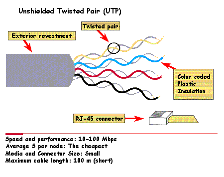
    UTP

    Are elements of the one layer. You can develop networks with different types of media. Each medium has its advantage and disadvantage, considering aspects such as the length of the cable to use, the cost and ease of installation

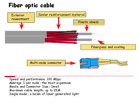
    Optical fiber

    The most commonly used medium is Category 5 Unshielded Twisted Pair Cable (UTP CAT 5)

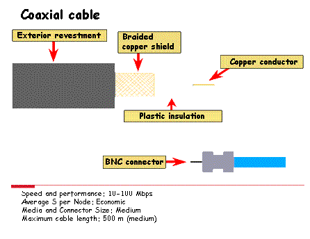
    Others also used are the coaxial cable and the fiber optic

    Coaxial cable

    Repeaters / HUBs

    When you have reached the limit of length of a medium, to use the elements known as repeaters to strengthen the signal, regenerating and retemporizando the same

    Are elements of the one layer, since they act only on the bit. Traditionally, it is considered an element with an input and an output, the repeaters of multiple ports is called a HUB

    The HUBs connect multiple cables, this increases the reliability, if it fails one of the means connected to it, only to fail that in particular, unlike a bus topology, in which all the elements use the same medium

    There are different classifications of HUBs, the first is whether they are assets or liabilities. Currently, almost all of them are active, that is, that need to be connected to the electrical supply to regenerate the signals

    Another classification are the HUB intelligent, or not intelligent. The HUB smart have console ports that allow you to program them to manage the network traffic. The not-smart to simply take the signal of the incoming network and repeated to each port, without regard to which

    The equivalent of the HUBs in the wireless network are access points (AP)

    Bridges

    A bridge is a device that is layer two which connects two network segments, filtering traffic to get that local traffic remains local, and at the same time be able to connect with the other segment

    The way to carry out this, it is discriminating for a list of MAC addresses that the bridge stores, to discern which are from a network or other

    The routers and switches have adopted many of the features of the bridge, but they continue to have great importance in the networks

    Switches

    A switch is an element of layer two, which is able to know for whom is the information passed by him in every moment, using the frame MAC, and act accordingly, only enviándosela to the interested

    This element significantly reduces the collisions that can occur in a same network segment or the same

    It is a good item to join small networks, will prevent the information of a network “bother” to other networks

    Some switches are highly configurable allowing, for example, create a VLAN to isolate different parts of a network from another

    If you can cope up to the price difference, they are preferred over hubs

    Routers

    The router is a device that is the layer three, therefore this device can make decisions based on groups of network addresses, in contrast to the MAC addresses

    The routers can serve to unite different technologies of layer 2. Given its breadth, to route packets based on layer 3, they have become the backbone of the Internet

    The purpose of a router is to examine incoming packets (layer data 3), to choose what is the best path for them through the network and then conmutarlos to the output port appropriate

    Router by software

    To perform the task of router, we can use other elements as may be a computer with multiple network cards

    The computer will do the functions of a router by means of the operating system and the installed software, an example of what is needed in a router is implemented in GNU/Linux would be:

    • One or more network cards installed and configured properly
    • The telnet service to allow remote configuration
    • Also the service is Routed, that will allow the routing
    • Enable IP_Forward in the kernel of the system

    And we only missing, add the appropriate paths

    Switches of layer 4 load balancers

    Load balancers help to improve the performance of the network by balancing efficiently load one or multiple servers

    This device helps to distribute the requests that a server can receive. For example, if we have three web servers, a load balancer will divide the requests between those three servers on the part of customers, in a percentage that you previously configured

    With its use, you can avoid overruns by part of a server, and spreads the work efficiently among all

    Gateway

    Gateway is a device that allows you to connect two networks, usually of a different protocol or a mainframe to a network

    Architecture of area networks to local

    The offer of local area networks is very wide, and there are solutions for almost any circumstance. We can select the cable type, topology, and even the type of transmission that more suit our needs. However, of all this offer the solutions more widely spread are the following three: Ethernet, Token Ring, and Arcnet

    Ethernet (IEEE 802.3)

    This network was originally developed by Xerox and Dec as a way of solving the problem of the wiring of networks. Its inventors were Robert Metcalf and David Boggs. According to Robert Metcalfe, the name Ethernet comes from the word Ether, which called poetically to a material non-existent, which, according to some ancient theories, it filled the space and acted as a support for the propagation of the energy through the universe

    The Ethernet standard also known as IEEE 802.3, uses a logical topology and bus topology-physical star or bus

    Originally used coaxial cable , although today it is usually used UTP cable. The speed of transmission of information by the cable is 10 Mbps. Today with Fast Ethernet, also called 100BASEX, working at speeds of 100 Mbps

    The Ethernet networks use the method CSMA/CD (Carrier Sense Multiple Access with Collision Detection) for access to the medium

    Token Ring (IEEE 802.5)

    Although IBM already had previously marketed the local area network called a Cluster (in base-band, with coaxial cable, to 375 Kbps and up to a maximum of 64 computers) and PC Network (broadband, 2 Mbps and up to a maximum of 72 computers), it was not until the year 1985 when IBM announced its local network to more sophisticated : the Token Ring, which is a network ring token-passing

    The different computers in the network are connected to the multistation access units, MAU (Multistation Access Unit), within which the ring is formed

    Up to 8 workstations can be connected to each MAU, and can have a maximum of 12 MAUs, therefore a maximum of 96 stations

    The maximum distance between the computer and the MAU is 50 meters (although you could reach up to 350 meters with higher quality cables), and between MAU is 135 meters (being able to reach 215 meters)

    The cable that is normally used is twisted pair, with or without shielding, although coaxial cable or fiber optic

    Arcnet

    It is a network base band, which transmits at a speed of 2.5 Mbps, with a topology hybrid star/bus. This system was developed in 1978 by the company Datapoint, although it was powered in the world of microcomputers by the company Standard Microsystems

    Arcnet is based on a scheme of step signal (token passing) to manage the flow of data between the nodes of the network

    All of the computers on the network are connected in star to a central dispatcher called the HUB active. The maximum distance between the computer and the HUB active must be less than 660 meters. The HUB's assets may also be connected to HUB liabilities, by connecting a maximum of 3 computers to each passive HUB. The maximum distance between a workstation and a passive HUB is 17 meters. You can connect more than one HUB is active, distancing himself between them to a maximum of 660 meters. In total, the maximum number of work stations must not be greater than 255

    Subnets

    When a LAN grows, it may be necessary or advisable for the traffic control of the network, it is divided into smaller pieces called network segments (or simply segments)

    As a result, the network is transformed into a group of networks, each of which needs an individual address

    Routers join or interconnect network segments or entire networks, taking logical decisions regarding the best path for sending data through an internetwork, and routing the packets to the segment and the output port suitable

    Connection of a local network to the Internet

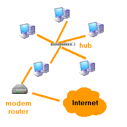
    Basically the connection will be with a modem or a router that will allow us to connect to the lines-PSTN, ISDN, ADSL or cable

    Modem Router

    The connection can be single-user, that is to say, only a position in our network has direct connection to the Internet, or multi -, in which through a router, all connected to the Internet. The router can operate in single-user or multi-seat. In the connection desktop, this is received by a team of our network and the operation is the same as in the case of a modem

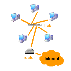
    Router

    In both cases, each computer will have an IP address of the local network. This address must be one of the values reserved for local networks

    In the first case, the computer that connects to the Internet, you will get a public IP

    To share your connection with other computers you must do the routing and masking, that is to say, must be able to distinguish the IP requests from the Internet to the local network and you need to mask the requests of other computers as their own, and then pass the response to the team that has made

    Yes the computer that connects to it runs under GNU/Linux, its IP address is defined as a gateway on the other computers. If the computer that connects to it runs under Windows, you often use software called a proxy, they configure each program to use the proxy

    In the second case, the router will have two IP addresses, one local network and the public Internet that get by the connection. The router will perform routing and masking, and is set as the gateway on the other computers of the network

    In the first case, the computer with connection, you can offer services of the Internet with its public IP. Can be mounted on a web server, an FTP server , a mail server...

    In the second to move services to computers on the network, using the protocol NAT (Network Address Translation). In such a protocol is configured, the requests for the port, indicating the IP address and port of the computer to which should be moved

    The topology of the local networks

    The topology is the geometric form of placing equipment and cables that connect them

    There are three possible ways of connection:

    • Point-to-point
      It will join two computers without going through an intermediate computer
    • Multipoint
      Multiple computers share a single cable
    • Logic
      The computers communicate with each other, whether or not there is physical connection directly between them

    The study of the topology is based on finding the most economic and efficient way of connecting all users to all resources of the network, while guaranteeing the reliability of the system and wait times low

    When the local networks are not too small, it is common for the mixture of topologies, giving place to other as a the star extended, a tree or hierarchical

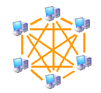
    Topology in the mesh

    This topology is used when there can be no interruption in communications. So, each computer has its own connection to the other computers. This is also reflected in the design of the Internet, which has multiple routes to any location

    Evidently, it is the topology that is most expensive for the amount of cabling and connection devices required. Is usually set between teams that need uninterrupted connection

    Topology in the mesh

    Topology in bus

    Uses a single segment to which all the computers are connected directly. Is the network of minor wiring. It was the most initially used on a small local network. Its biggest drawback is that if a link fails, fails across the network. Sometimes used for backbone connections, for example, to connect different floors of a building

    Topology in bus

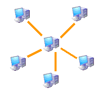
    Star topology

    Connects all computers to a central computer through a point to point connection. The teams pass the information to the central computer and relayed to the computer to which it is addressed. If the central computer fails, it obviously fails the entire network. The central computer is a server and requires the maintenance of specialized staff. The size and capacity of the network are directly related to the ability of the core team

    A star topology extended connects individual stars together by connecting hubs or switches. This topology can extend the scope and coverage of the network

    Star topology

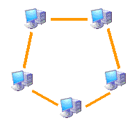
    Ring topology

    This topology connects a computer with the following, and the last with the first, that is to say, they form a circle of point to point connections between computers contiguous. The messages go from one computer to another until it reaches the proper

    The communications protocol must avoid conflicting situations when using the shared medium. Sometimes there is a control center which assigns the shift of communication

    Ring topology

    Logical topology

    The logical topology of a network is the way computers communicate through the medium

    The two types of topology most common are:

    • Topology broadcast
      Each computer sends its data towards all the other computers through the network. The stations do not follow any order to use the network, the order is the first thing that enters, the first thing that is served. This is the way it works Ethernet
    • Topology for transmission of tokens
      The transmission of the token controls the access to the network by transmitting a token-mail to each team sequentially. When the computer receives the token, it means that it is your turn to use the network. If you do not have data to send, it transmits the token to the next computer and the process is repeated

    Two examples of networks that use the transmission of tokens are Token Ring and the Interface of distributed data for fibre (FDDI). Arcnet is a variation of Token Ring and FDDI. Arcnet is the transmission of tokens in a bus topology

    The logical topology gives rise to the definition of protocols to establish how to perform the communication

    Wireless networks

    Wireless networks

    Wireless networks are those that communicate by an un guided (wireless) transmission by electromagnetic waves. Transmission and reception is done via antennas

    They have advantages such as rapid network installation without the need for cabling, allow mobility, and have fewer maintenance costs than a conventional network

    Types

    Depending on their coverage, they can be classified into different types:

    Types of wireless networks

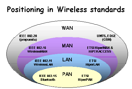
    • WPAN (Wireless Personal Area Network)
      In this type of personal coverage network, there are different technologies:

      • HomeRF
        Standard for connecting all mobile phones of the house and the computers through a central apparatus
      • Bluetooth
        Protocol following IEEE 802.15.1 specification
      • ZigBee
        Based on the IEEE 802.15.4 specification and used in applications such as home automation, which require secure communications with low data transmission rates and maximizing battery life, low power consumption
      • RFID
        Remote data storage and retrieval system for the purpose of transmitting the identity of an object (similar to a unique serial number) using radio waves
      • WLAN (Wireless Local Area Network)
        In local area networks we can find the technologies:

        • HiperLAN (High Performance Radio LAN)
          A standard group ETSI
        • Wi-Fi
          Follow IEEE 802.11 standard with different variants
        • WMAN (Wireless Metropolitan Area Network, Wireless MAN)
          For metropolitan area networks there are technologies:

          • WiMax (Worldwide Interoperability for Microwave Access)
            Worldwide Interoperability for Microwave Access is a wireless communication standard based on the IEEE 802.16 standard. WiMax is a protocol similar to Wi-Fi, but with more coverage and bandwidth. We can also find other communication systems such as LMDS (Local Multipoint Distribution Service)
          • WWAN (Wireless Wide Area Network, Wireless WAN)
            In these networks we find the technologies used in mobile phones:

            • GPRS (General Packet Radio Service)
              The transmission is digital
            • 0G
              Group of technologies used before the worldwide dissemination of mobile phones, usually military, in the United States, Canada, Finland, Sweden, Denmark, Spain, Philippines, Jamaica, Cuba, Chile, etc.
            • 1G
              Set of standards followed in the 1980s for mobile phone transmission, including NMT (Nordic Mobile Telephone) used in the Nordic countries; AMPS in the United States;
              TACS (Total Access Communications System) in the United Kingdom; C-450 in East Germany, Portugal and South Africa; TMA in Spain; Radiocom 2000 in France and RTMI in Italy. Multiple systems were implemented in Japan; three standards, TZ-801, TZ-802, TZ-803, developed by NTT, with a competition system operated by DDI using the JTACS standard
            • 2G
              A set of standards followed in the 1990s for mobile phone transmission, digital telephony protocols were introduced that, in addition to allowing more simultaneous links in the same bandwidth, allowed other services to be integrated into the same signal, such as sending text or page messages into a service called Short Message Service (SMS) and greater ability to send data from fax and modem devices. These included GSM (Global System for Mobile Communications); Cellular PCS/IS-136, known as TDMA (also known as TIA/EIA136 or ANSI-136) System regulated by the Telecommunications Industry Association or TIA; IS-95/cdmaONE, known as CDMA (Code Division Multiple Access); D-AMPS Digital Advanced Mobile Phone System; PHS (Personal Handyphon System) System originally used in Japan by NTT; DoCoMo in order to have a standard focused more on data transfer than the rest of the 2G standards
            • 3G
              Set of standards that replaced 2G by adding protocols for voice and data over mobile telephony using UMTS (Universal Mobile Telecommunications System). 3G technologies are the answer to the International Telecommunication Union's IMT-2000 specification. In Europe and Japan, the UMTS (Universal Mobile Telecommunication System) standard was selected, based on W-CDMA technology. UMTS is managed by the 3GPP organization, also responsible for GSM, GPRS and EDGE. 3G also envisaged the evolution of 2G and 2.5G networks. GSM and TDMA IS-136 that were replaced by UMTS, cdmaOne networks evolved to CDMA2000
            • 4G
              A set of standards that replaced 3G, the International Telecommunication Union (ITU) created the IMT-Advanced committee that defined its requirements. Among the technical requirements: Maximum data transmission speeds must be between 100 Mbit/s for high mobility and 1 Gbit/s for low mobility. The 3GPP (Long Term Evolution) LTE (Long Term Evolution) standard is not 4G because it does not meet the requirements defined by IMT-Advanced in peak transmission speed and spectral efficiency characteristics. However, ITU stated in 2010 that 4G candidates, such as that, could advertise as 4G. It is based entirely on the IP protocol, being a system and a network, which is achieved thanks to the convergence between cable and wireless networks. The WWRF (Wireless World Research Forum) intended 4G to be a fusion of technologies and protocols, not just a single standard, similar to 3G, that included technologies such as GSM and CDMA.1. NTT DoCoMo in Japan was the first to conduct experiments with fourth generation technologies, reaching 100 Mbit/s in a vehicle at 200 km/h. The firm launched the first 4G LTE technology-based services in December 2010 in Tokyo, Nagoya and Osaka
            • 5G
              Set of standards that are expected to replace 4G. It is expected to be common use by 2020. Swedish company Ericsson has managed to reach real 5 Gbps speeds, with live demonstrations of the pre-standard (pre-standard) 5G network technology standard. In November 2014, Huawei announced the signing of an agreement with Russian mobile operator Megafon to standardize and develop 5G test networks, in view of the 2018 FIFA World Cup

    Features

    Depending on the frequency range used to transmit, the means of transmission can be radio waves, terrestrial or satellite microwaves, and infrared, for example. Depending on the media, the wireless network will have some features or others:

    • Radio waves
      Electromagnetic waves are omnidirectional, so satellite dishs are not required. Transmission is not sensitive to rain attenuations as it operates at not too high frequencies. In this range are the bands from the ELF ranging from 3 to 30 Hz, to the UHF band ranging from 300 to 3000 MHz, that is, it comprises the radio spectrum of 30 – 3000000 Hz
    • Terrestrial microwave
      Parabolic antennas with a diameter of approximately three meters are used. They have a coverage of kilometers, but with the disadvantage that the emitter and receiver must be perfectly aligned. Therefore, they are used to use in point-to-point links over short distances. In this case, rain attenuation is more important as it is operated at a higher frequency. Microwaves comprise frequencies from 1 to 300 GHz
    • Microwave satellite
      Links are made between two or more ground stations called base stations. The satellite receives the signal (called an upstream signal) in one frequency band, amplifies it and relays it in another band (downstream signal). Each satellite operates in specific bands. The frequency boundaries of microwaves, both terrestrial and satellite, with infrared and high-frequency radio waves mix quite a bit, so there may be interference with communications at certain frequencies
    • Infrared
      Transmitters and receivers that modulate non-consistent infrared light are linked. They must be aligned directly or with a reflection on a surface. They can't get through the walls. Infrared ranges from 300 GHz to 384 THz

    Applications

    • The most important bands with wireless applications, of the frequency range covering radio waves, are VLF (navigation and submarine communications), LF (long wave AM radio), MF (medium wave AM radio), HF (shortwave AM radio), VHF (FM radio and TV), UHF (TV)
    • Using terrestrial microwaves, there are different protocol-based applications such as Bluetooth or ZigBee to interconnect laptops, PDAs, phones, or other devices. Microwaves are also used for radar communications (speed detection or other remote object characteristics) and for DDT (digital terrestrial television)
    • Satellite microwaves are used for satellite television broadcasting, long-distance telephone transmission and private networks
    • Infrared has applications such as short-distance communication of computers with their peripherals. They are also used for remote controls, as they do not interfere with other electromagnetic signals, for example the television signal. One of the most commonly used standards in these communications is the IrDA (Infrared Data Association). Other uses of infrared are techniques such as thermography, which allows to determine the temperature of objects remotely

    Wi-Fi

    Wi-Fi

    Wi-Fi (which stands for “Wireless Fidelity”, sometimes incorrectly abbreviated WiFi) is the name of the certification granted by the Wi-Fi Alliance, formerly WECA (Wireless Ethernet Compatibility Alliance), a group that guarantees compatibility between devices that use the 802.11 standard

    The IEEE 802.11 specification (ISO/IEC 8802-11) is an international standard that defines the characteristics of a WLAN

    Due to improper use of the terms (and for marketing reasons) the name of the standard is confused with the name of the certification

    A Wi-Fi network is actually a network that complies with the 802.11 standard

    To devices certified by the Wi-Fi Alliance they are allowed to use this logo:

    Logo Wifi

    With Wi-Fi you can create high-speed wireless local area networks as long as the equipment to be connected is not too far from the access point

    In practice, Wi-Fi supports laptops, desktops, personal digital assistants (PDAs), or any other type of high-speed device with high-speed connection properties (11 Mbps or faster) within a radius of several dozens of meters indoors (20 to 50 meters generally) or within a radius of hundreds of meters outdoors

    Wi-Fi providers are beginning to cover areas with a high concentration of users (such as train stations, airports, and hotels) with wireless networks. These areas are called “local coverage zones”

    The 802.11 standard sets the lower levels of the OSI model for wireless connections that use electromagnetic waves, for example:

    • The physical layer (sometimes abbreviated "PHY" layer) offers three types of information encoding
    • The data binding layer consisting of two sublayers: Logical Binding Control (LLC) and Media Access Control (MAC)

    The physical layer defines the modulation of radio waves and signaling characteristics for data transmission while the data link layer defines the interface between the computer bus and the physical layer, in particular an access method similar to that used in the Ethernet standard, and the rules for communication between network stations. Actually, the 802.11 standard has three physical layers that set alternative transmission modes:

    Data Binding Layer (MAC) 802.2
    802.11
    Physical cover (PHY) DSSS FHSS Infrared

    Any higher level protocol can be used on a Wi-Fi wireless network in the same way it can be used on an Ethernet network

    Wifi standards

    The original 802.11 standard, which allows 1 to 2 Mbps bandwidth, has been modified to optimize bandwidth (including 802.11a, 802.11b, and 802.11g standards, called 802.11 physical standards) or to specify components better to ensure greater security or compatibility. The table below shows the various modifications to the 802.11 standard and its meanings:

    Name of the standard Name Description
    802.11-1997 802.11 The 802.11-1997 standard is the original version of the 802.11 standard, specifying two "theoretical" transmission rates of 1 and 2 Mbps that are transmitted over infrared (IR) signals. It also defines the carrier sense multiple access with collision avoidance (CSMA/CA) protocol as an access method. Many of his weaknesses were corrected in the 802.11b standard
    802.11a Wi-fi 5 The 802.11a standard (called Wi-Fi 5) supports higher bandwidth (the maximum total throughput is 54 Mbps although in practice it is 30 Mbps). The 802.11a standard provides eight radio channels in the 5 GHz frequency band
    802.11b Wi-fi 1 The 802.11 standard offers a maximum total throughput of 11 Mbps (6 Mbps in practice) and has a range of up to 300 meters in an open space. Uses the 2.4 GHz frequency range with three radio channels available
    802.11c Combination of 802.11 and 802.1d The combined standard 802.11c offers no interest to the general public. It is only a modified version of the 802.1d standard that allows you to combine the 802.1d with 802.11 compatible devices (at the data binding level)
    802.11d Internationalization The 802.11d standard is a complement to the 802.11 standard that is intended to allow international use of local 802.11 networks. Allows different devices to exchange information in frequency ranges based on what is allowed in the device's home country
    802.11e Improvement of the quality of the service The 802.11e standard is intended to improve quality of service at the data binding layer level. The goal of the standard is to define the requirements of different packets in terms of bandwidth and transmission delay to allow better audio and video transmissions
    802.11f Roaming 802.11f is a recommendation for access point vendors that makes products more compatible. It uses the IAPP protocol that allows a roaming user to clearly switch from one access point to another while on the move regardless of the branding of access points used in the network infrastructure. This property is also known simply as roaming
    802.11g The 802.11g standard offers high bandwidth (with a maximum total throughput of 54 Mbps but 30 Mbps in practice) in the 2.4 GHz frequency range. The 802.11g standard is compatible with the above standard, the 802.11b, which means that devices that support the 802.11g standard can also work with the 802.11b
    802.11h The 802.11h standard aims to combine the 802.11 standard with the European standard (HyperLAN 2; 802.11h h) and comply with European regulations related to frequency use and energy performance
    802.11i The 802.11i standard is intended to improve security in data transfer (by managing and distributing keys, and by implementing encryption and authentication). This standard is based on the AES (Advanced Encryption Standard) and can encrypt transmissions running on 802.11a, 802.11b and 802.11g technologies
    802.11Ir The 802.11Ir standard was developed so that you can use infrared signals. This standard has become technologically obsolete
    802.11j The 802.11 standard j it is for the regulation of japanese what the 802.11 h is to european regulation
    802.11k The 802.11k standard allows wireless switches and access points to calculate and assess the radio frequency resources of clients in a WLAN network, improving their management. It is designed to be implemented by software, simply updating computers, as long as both clients (adapters and WLAN cards) and infrastructure (access points and WLAN switches) are supported
    802.11n Wi-Fi 4 The 802.11n standard (called Wi-Fi 4) was a proposed modification to the 802.11-2007 standard to significantly improve network performance beyond previous standards, such as 802.11b and 802.11g, with a significant increase in speed. maximum transmission rate of 54 Mbps to a maximum of 600 Mbps. Currently the physical layer supports a speed of 300 Mbps, using two streams on a 40 MHz channel. Depending on the environment, the user could obtain a throughput of 100 Mbps
    802.11p The 802.11p standard operates on the 5.90 GHz and 6.20 GHz frequency spectrum, designed with the idea of using it for communication between vehicles and with on-road infrastructure. It is the basis of dedicated short-range communications (DSRC). It also adds wireless access in vehicle environments (WAVE). This improvement is widely used in the implementation of Intelligent Transport Systems (SIT)
    802.11r Fast Basic Service Set Transition The 802.11r standard (called Fast Basic Service Set Transition) allows you to set security protocols that identify a device on the new access point before it leaves the current one and passes to it. This feature, which once enunciated seems obvious and indispensable in a wireless data system, allows the transition between nodes to take less than 50 milliseconds. This time lapse is short enough to maintain communication via VoIP without noticeable outages
    802.11v The 802.11v standard is used to allow remote configuration of client devices by allowing centralized (cellular network-like) or distributed station management through a data link layer (Layer 2) mechanism. This includes, for example, the network's ability to monitor, configure, and upgrade client stations. It also provides us with:

    • Energy saving mechanisms with handheld VoIP Wi-Fi devices in mind
    • positioning, to provide new location dependent services
    • timing, to support applications that require very precise calibration;
    • coexistence, which brings together mechanisms to reduce interference between different technologies in the same device
    802.11w The 802.11w standard is based on the 802.11i protocol and serves to protect WLAN networks against subtle attacks on WLAN frames. Not finished yet. TGw is working on improving the IEEE 802.11 media access control layer to increase the security of authentication and encoding protocols. Attempts are made to extend the protection provided by the 802.11i standard beyond data to management frames, responsible for the main operations of a network. These extensions will have interactions with IEEE 802.11r and IEEE 802.11u
    802.11ac Gigabit Wi-Fi The 802.11ac standard (called Gigabit Wi-Fi or Wi-Fi 5) was a modification of the 802.11n standard that consisted of improving transfer rates up to 433 Mbps, theoretically achieving rates of 1.3 Gbitps using 3 antennas. It operates within the 5 GHz band, expanding the bandwidth up to 160 MHz (in 802.11n networks it was 40 MHz), uses up to 8 MIMO streams and includes high-density modulation (256 QAM)
    802.11ax Wi-Fi 6 The 802.11ax standard (called Wi-Fi 6 or Wi-Fi 6th Generation by the Wi-Fi Alliance) is designed to operate in the existing 2.4 GHz and 5 GHz spectrums. It introduces OFDMA to improve overall spectral efficiency
    802.11be Wi-fi 7 The 802.11be standard (called Wi-Fi 7 or Extremely High Throughput (EHT) by the IEEE). It operates in all three bands (2.4 GHz, 5 GHz and 6 GHz) to fully utilize spectrum resources. While Wi-Fi 6 was created in response to the growing number of devices in the world, the goal of Wi-Fi 7 is to deliver amazing speeds to every device with greater efficiency. Wi-Fi 7 features 320 MHz ultra-wide bandwidth, 4096-QAM, Multi-RU and Multi-Link operation to provide speeds 4.8 times faster than Wi-Fi 6 and 13 times faster than Wi-Fi 5

    It is also important to mention the existence of a standard called "802.11b+". This is a patented standard that contains improvements over data flow. On the other hand, this standard has some interoperability gaps because it is not an IEEE standard

    Range and data flow

    The 802.11a, 802.11b, 802.11g, 802.11n, 802.11ac, 802.11ax, 802.11be standards, called “physical standards”, are modifications of the 802.11 standard and operate in different modes, which allows them to achieve different transfer speeds of data according to their ranges

    Date IEEE Standard Vel. max data Bands Channel size Modulation Antennas
    1997 802.11b (WI-FI 1) 1 o 2 Mbps 2.4 GHz 20 MHz
    1999 802.11a (WI-FI 2) 54 Mbps 5 GHz 20 MHz
    2003 802.11g (WI-FI 3) 54 Mbps 2.4 GHz 20 MHz
    2009 802.11n (WI-FI 4) 600 Mbps 2.4 y 5 GHz 20, 40 MHz
    2013 IEEE 802.11ac (WI-FI 5) 3.5 Gbps 2.4 y 5 GHz 20, 40, 80, 80+80, 160 MHz OFDM 256-QAM 4×4 MIMO DL MIMO
    2019 802.11ax (WI-FI 6) 9.6 Gbps 2.4 y 5 GHz 20, 40, 80, 80+80, 160 MHz 1024-QAM OFDMA 8×8 UL/DL MU-MIMO
    2021 802.11ax (WI-FI 6E) 9.6 Gbps 2.4, 5 y 6 GHz 20, 40, 80, 80+80, 160 MHz 1024-QAM OFDMA 8×8 UL/DL MU-MIMO
    2024 (possibly) 802.11be (WI-FI 7) 46 Gbps 2.4, 5 y 6 GHz Up to 320MHz 4096-QAM OFDMA
    (with extensions)
    16×16 UL/DL MU-MIMO

    Fiber optic

    Fiber optic

    Optical fiber is a flexible fiber that transmits light between two ends of a fiber and allows transmission over larger distances and bandwidth (data rate) than electrical cables.

    It is one of the most commonly used guided transmission media (especially in recent times) for high-speed data transmission or for long distances.

    Its low attenuation and immunity to electromagnetic interference (transmits optical and non-electrical pulses) makes it ideal for data transmission in operator and large enterprise environments.

    Although initially its cost was higher, it is already fully competitive with other means of transmission (coaxial cables and twisted pair) since it is also a light cable and easy to install

    The optical transmission system

    Optical fiber is a cable formed by one or more fiberglass wires through which a beam of light travels.

    Optical fiber is based on the principle of optical transmission

    This principle is based on confining a light signal within a glass conductive wire (core) using an outer layer that reflects the transmitted light causing it to remain confined within the nucleus.

    The Snell's Law relates the angles of refraction of light in a change of medium with the refractive indices of each medium, using the following formula:

    n_1\cdot \sin\left( \phi_1 \right) = n_2\cdot \sin\left( \phi_2 \right)

    Being n_1 and n_2 the refractive indices of the transmission media: core and cover respectively

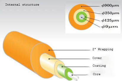
    During the manufacturing process of the fiber, these are coated with a protection of 250 \mu m, covering the core and cover assembly

    This protection ensures minimal non-deformability and hardness for use in transmission systems

    On this protection is also applied a coating that can be two types:

    • Loose tube fibers

      it is mainly used for outdoor installations, since the cable is exposed to temperature changes where the coating allows some slack in the case of expansion

    • Tight coating fiber

      it is used in indoor environments and is completely covered by a plastic protection of 900 \mu m

      Being more sensitive to temperature changes by not allowing the expansion of its components without affecting their transmission properties

    Constructive characteristics

    It is one composed of one or more glass threads forming a structure with the following format:

    • A fiber core (glass wire) with a high refractive index
    • A cover covering the core of similar material but with a lower refractive index
    • A wrap that isolates the fibers and prevents interference between them in addition to protecting the kernel

    The information must be converted into beams of lights (by means of Led or Laser emitting devices and optical receivers at their ends)

    Internal structure

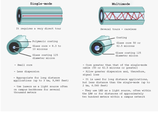
    One of the basic parameters in optical fiber is the relationship or ratio between the core and cover refractive indices, giving rise to two types of fiber:

    • Single-mode

      the relationship of core and cover refractive indices only allows the transmission of a single transmission mode

      Hence its single-mode name. A mode can be interpreted as a single transmission channel

      High performance is achieved by not having intermodal interference reaching large bandwidth of around 50 and 100 Ghz

    • Multimode

      the ratio of core and cover refractive indices allow transmission of various transmission modes

      Hence its multimode name

      The propagation of several transmission modes causes intermodal dispersion to appear which translates into worse transmission performance and as a consequence lower transmission speed reaching 1 Ghz

      Within multimode fibers there are two types:

      • index jump
      • gradual index

    Multimode single-mode difference

    Transmission features

    Fiber has a number of features that make it ideal for high-speed data transmission

    These features mainly are:

    • High bandwidth (around 50 and 100 Gps) for voice, data, video, etc
    • Very low attenuation with distance (0.1 dB/km), ideal for long distances
    • Low error rate, BER < 10-11 so the transfer rate that can be obtained is very high
    • Immune to electromagnetic interference, as it transmits beams of light and not electrical impulses
    • Corrosion resistant and good temperature performance

    These properties are common to the different types of existing fiber (single-mode and multimode) although as already mentioned above, in the case of single-mode the bandwidth that is reached is greater than in multimode

    Applications: Use of frequencies

    Fiber optics presents a series of commercial formats where each of them has unique characteristics that make them appropriate for one application or another

    These commercial formats are as follows:

    Commercial formats
    Type of optical fiber Trade name Core/cover diameter Maximum distance
    Gbps Applications
    Multimode
    OM1 65,5 / 125 \mu m 32 m
    OM2 50 / 125 \mu m 85 m
    OM3 50 / 125 \mu m 300 m
    OM4 50 / 125 \mu m 550 m
    Single-mode
    OS1 50 / 125 \mu m 2 km
    OS2 50 / 125 \mu m 10 km

    In practice, the standard formats OM1 and OM2 are deused so only om3 and om4 formats are used for the vast majority of installations

    OS1 and OS2 formats are used for long distances

    Types of joints: Advantages and disadvantages

    Different types of joints are used, more common are:

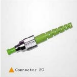
    • FC Connector FC

      used for long-range fibres

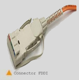
    • FDDI Connector FDDI

      used for medium and long-range connections

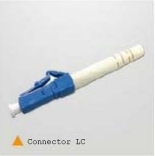
    • LC Connector LC

      is best suited for data transmission at high speeds

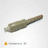
    • SC Connector SC

      is the most used for mid-range data transmission

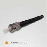
    • ST Connector ST

      widely used for security systems

    Among all of them, sc and lc formats are the most widely standardized

    To transmit light signals through optical fibers, an emitting element is required at the beginning that converts the electrical signals into optical (I/O) and another at its end that converts the optical signals into electrical ones again (O/E)

    Electro-optical converters are manufactured based on the combination of the following elements: Indium (In), Gallium (Ga), Germanium (Ge), Silicon (Si), Arsenic (As), Phosphorus (P), which have proven to be the most suitable for the manufacture of these devices

    Semiconductor technology made it possible to build small, low-cost light emitters and detectors

    There are two options of semiconductor sources to be used in optical fibers as light emitters:

    • LED diodes

      It is a diode of semiconductor material that forms a P-N junction of the same characteristics as a conventional diode of germanium or silicon

      The main difference with conventional diodes is that certain materials that are used as dopators in the LED are chosen in such a way that the electronic recombination process is radioactive and light is generated.

      Depending on the material used in its manufacture, led diode will emit visible light or another color

      Due to the large scattering of light and the wide spectral distribution of an LED diode, it is used only when transmissions are required at short distances and with little power output.

      They are relatively inexpared and have a very long shelf life (107 hours)

    • Laser Diode

      The LASER is basically a semiconductor diode that when polarized directly emits a coherent, monochromatic and very narrow light in its spectral width, from 1 to 5 mm

      This light, due to its narrow spectrum, does not scatter as much as the light produced by LED diode, so it can be used efficiently for transmissions over a long distance and at frequencies well above 300 Mhz

      It is a more expensive device than the LED diode but is used for transmissions over long distances, although today with its wide diffusion and for reasons of economy of scale its price is already competitive with the LED diode

    For the reception of optical signals and their conversion to electrical signals, optical receiver devices are used, which can be of two types:

    • Phototransistors

      They are receivers that have good sensitivity but are not suitable for high speed rates

    • Photodiodos

      They are semiconductor diodes but inversely polarized with which they act as optical to electric converters

      They are low latency devices, very fast, high sensitivity and that make it very suitable for high speed transmissions

      They are further classified into two types:

      • Pin photodiode
      • APD photodiode

    Routing

    Routing

    The routing is the function of searching for a path among all the possible in a packet network whose topologies have a great connectivity

    Given that it's about finding the best possible route and in consequence what is the metric that should be used to measure it

    The network must find a route using:

    • Efficiency
    • Flexibility

    The switches of the network are organised in a tree structure

    Routing static uses the same approach all the time

    The routing dynamic allows for changes in routing depending on traffic

    Uses a structure of relationship peer-to-peer nodes

    Criteria of routing

    Routing alternative

    Of the possible routes between two central end are predefined

    It is the responsibility of the switch source to select the appropriate route for each call

    Each switch has a set of pre-set routes, in order of preference

    A different set of routes preplanificadas in moments different of time

    Two types:

    • Alternative fixed
      Only a sequence of routing for each couple source-destination
    • Alternative dynamic
      Different set of routes preplanificadas in moments different of time

    Routing in packet-switched networks

    One of the most complicated and crucial aspects of the design of packet-switched networks is related to the routing

    Features required:

    • Accuracy
    • Simplicity
    • Robustness
    • Stability
    • Impartiality
    • Optimization
    • Efficiency

    Performance criteria

    It is used for the choice of a route

    Two fundamental techniques:

    • Choosing the path with the fewest hops: Minimize network resource consumption
    • A generalization of the above is the criterion of the minimum cost
      • In case of different link costs, the path that is the minimum cost will be taken
      • If each node has equal cost, we can generalize this criterion by looking for the path of least number of hops

    Moment and place of decision

    • Instant
      • Packet or datagram
        If costs change, the next packet can follow a different route, again determined by each node along the way
      • Virtual circuit
        Each node remembers the routing decision made when the virtual circuit was established, so that it is limited to transmitting packets without making new decisions
    • Place
      • Routing distributed
        • Is carried out for each node
        • It is the most robust
      • Routing centralized
      • Routing from the source

    Source of information on the network and time of update

    Routing decisions are usually made based on network knowledge, load, and link cost (but not always such as flooding and random routing)

    • Routing distributed
      • Nodes make use of local information (cost associated with each output binding)
      • They can use information from adjacent nodes (congestion between them)
      • Can get information from all nodes on a potential route of interest
    • Routing central
      • Collect information from all nodes
    • Update time
      • When the nodes have updated information of the network
      • For a static routing strategy, the information is never updated
      • For an adaptive technique, the update is carried out periodically

    Strategies of routing ARPANET

    First generation: 1969

    • Adaptive algorithm distributed
    • Estimation of the delays as a criterion of operation
    • Algorithm of Bellman-Ford
    • Each node exchanges its vector of delay with all of its neighbors
    • Table routing updated based on the input information
    • It does not take into account the speed of the line, but the length of the tail
    • The length of the tail is not a good measure of the delay
    • Responds slowly to congestion

    Second generation: 1979

    • It makes use of the delay as performance criterion
    • The delay is measured directly
    • Algorithm of Dijkstra
    • It is good in low loads or moderate
    • In the face of high loads, there is little correlation between the indicated and experienced delays

    Third generation: 1987

    • Change the estimates of the cost of the link
    • Average delay measurement in last 10 seconds
    • It is normalized on the basis of the current value and previous results

    Strategies of routing

    Routing static

    A single-path permanent for each pair of nodes source-destination in the network

    Determining the routes by using either of the algorithms of routing for minimum cost

    Routes are fixed, at least as long as the network topology is

    Example of routing static

    Matrix routing central

    {\tiny\text{Destination node}}\overset{\text{Source node}}{\begin{pmatrix}& 1& 2& 3& 4& 5& 6 \\ 1& & 1& 5& 2& 4& 5 \\ 2& 2& & 5& 2& 4& 5 \\ 3& 4& 3& & 5& 3& 5 \\ 4& 4& 4& 5& & 4& 5 \\ 5& 4& 4& 5& 5& & 5 \\ 6& 4& 4& 5& 5& 6 \\ \end{pmatrix}}

    Node Table 1
    Destination Following node
    2 2
    3 4
    4 4
    5 4
    6 4
    Table of Node 2
    Destination Following node
    1 1
    3 3
    4 4
    5 4
    6 4
    Node 3 table
    Destination Following node
    1 5
    2 5
    4 5
    5 5
    6 5
    Node Table 4
    Destination Following node
    1 2
    2 2
    3 5
    5 5
    6 5
    Node 5 table
    Destination Following node
    1 4
    2 2
    3 3
    4 4
    6 6
    Node Table 6
    Destination Following node
    1 5
    2 5
    3 5
    4 5
    5 5

    Flooding

    It does not require any information about the network. A source node sends a packet to all its neighbor nodes. Neighboring nodes, in turn, transmit it over all output links except the one that arrived. Finally, a number of copies will arrive at the destination

    Each packet contains a unique identifier, so duplicates can be discarded. In this way, one technique would be for nodes to be able to remember the identity of the packets they have previously retransmitted, so that network loads are avoided

    Another simpler technique is that a hop count field can be included in each packet, a lifetime where each time a node transmits a packet, it decrements the count by 1, so that when the counter reaches the zero value of remove the packet from the network

    Properties

    • All possible paths between the source and destination nodes are tested. What offers us robustness
      Example: Sending a high priority message to ensure that the package is received
    • At least one copy of the packet to be received at the destination will have used a lower hop path. It could be used initially to establish the route for a virtual circuit
    • All nodes are visited. It can be useful to carry out the propagation of relevant information for all nodes (for example, a central routing table)

    Example of flood

    Flood

    Routing random

    A node selects a single outbound path to retransmit an incoming packet. Selection can be done randomly or alternately

    An improvement is that you can select the output path in accordance with the calculation of probabilities

    You do not need to use information about the network. In general, the route will not correspond to the one with the least cost or the one with the fewest number of jumps. It has less traffic than Flooding but is equally simple and robust. A node selects a single outgoing path to retransmit an incoming packet. Selection can be done randomly or alternately

    An improvement is that you can select the output path in accordance with the calculation of probabilities

    You do not need to use information about the network. In general, the route will not correspond to the one with the least cost or the one with the fewest number of jumps. It has less traffic than the flood one but is equally simple and robust

    Routing adaptable

    Virtually all packet-switched networks used some kind of technique of transmission adaptive

    Routing decisions change as network conditions change:

    • Failures
    • Congestion

    It requires information about the state of the network presenting disadvantages:

    • Decisions are more complex: higher processing cost at network nodes
    • It is necessary for the nodes to exchange information about the status and traffic of the network: increased traffic and degradation of network performance
    • The reaction too quickly can cause oscillation or be too slow to be relevant

    Advantages of routing adaptive

      • Improvement of the performance
      • It is helpful in the control of the congestion
      • Complex system: Theoretical benefits may not be met

    Classification

    Classification made in accordance with the source of the information

        • Local (isolated)
          • Route the packet to the output link with the tail shorter
          • You can include a weight for each destination. They are rarely used, since they do not easily exploit the information available
        • Adjacent nodes
        • All nodes

    Example of routing adaptive isolated

    Isolated Adaptive Routing Example

    Petri

    Petri

    A Petri net is a mathematical or graphic representation of a discrete event system in which the topology of a distributed, parallel or concurrent system can be described

    The essential Petri net was defined in the 1960s by Carl Adam Petri

    They are a generalization of automata theory which allows to express a system of events concurrent

    A Petri net is made up of places, transitions, directed arcs and marks or tokens that occupy positions within the places

    The rules are: Arches connect a place to a transition as well as a transition to a place

    There can be arcs between places or between transitions

    The sites contain a finite number or countable infinity of marks

    Transitions are triggered, that is, they consume marks from a start position and produce marks at an end position. A transition is enabled if it has marks at all its input positions

    In its most basic form, the marks that circulate in a Petri net are all identical

    A variant of Petri nets can be defined in which the marks can have a color (information that distinguishes them), an activation time and a hierarchy in the network

    Most of the problems on Petri nets are decidable, such as the limited nature and the coverage

    To solve them, a Karp-Miller tree is used. The scope problem is known to be decidable, at least in exponential time

    Useful in the qualitative analysis

    Petri nets can be used to perform the qualitative analysis of a network, since they are bipartite graphs

    Depending on how we analyze the Petri net, we can find:

    • Structural analysis (depend on the structure)
      They have the following properties:

      • Repetitive
        There is a sequence of shots, including all transitions, that if they can be triggered leave the system the same as at the beginning \Longleftrightarrow There is a vector that is null right of the matrix of incidence with all its terms positive integers
      • Conservative
        There is a combination of positive integer weights that if applied to the places, the sum of the marking of all the places weighted by their weights is invariant (always the same) \Longleftrightarrow There exists a vector null left of the matrix of incidence with all its terms positive integers
      • Locks
        Place or set of places in which the marks they contain cannot diminish, because the exit transitions of those places are also entrance, with greater total weight in the entrance arches (to the places of the trap) than the output. A row or sum of rows with negative or zero values in the incidence matrix, will contain a lock
      • Traps
        Place or set of places where the marks they contain cannot increase, because the entry transitions to those places are also exiting, with greater total weight in the exit arches (of the trap places) than the input. A row or sum of rows with positive or zero values in the incidence matrix, will contain a trap
      • Lock / Trap
        It is both a lock and a trap. A row or sum of rows with all zero values in the incidence matrix, will contain a lock / trap
    • Dynamic analysis (depend on the initial markup)
      They have the following properties:

      • Cyclic
        Given an initial state, from any accessible state you can always return to the initial state
      • Live
        Given an initial state, from any accessible state there will never be a transition that can no longer be triggered later
      • Limited
        All places have an upper bound finite

    The Simplex Method

    The Simplex Method

    The Simplex method can be used to solve problems of maximizing or minimizing a linear function of variables, with constraints in the form of equalities or inequalities of linear functions of those variables, and with all variables dimensioned above or below

    Applying the following steps:

    1. Statement of the problem in standard form
    2. Application of the Simplex algorithm
    3. Determination of the solution obtained

    Step 1: Approach the problem as standard

    1. The function should be set to "minimize"
    2. If necessary, variable changes are made so that all variables have 0 as the lower dimension (X_i\geq 0, \forall i)
    3. The restrictions are put with the constant term positive
    4. Become the inequalities of the constraints into equalities by adding the slack variables
    5. Artificial variables are added to constraints that do not have a variable at the base, and the sum of those artificial variables multiplied by M (which is considered with a very high value) is added to the target function.
    6. The table is populated to apply the Simplex algorithm. Its structure is as follows:
      X_1 \cdots X_n
      X basic to b
      c-z

      X_1 \cdots X_n is the alignment of the original variables, slack variables and artificial variables

      to are the terms of such variables in the constraints

      b are the constant elements of such constraints (on the other side of variables in equality)

      c - z are marginal costs, where c are the coefficients of the target function, and z_i=c_{b_1}\cdot a_{1 j}+\cdots+c_{b_m}\cdot a_{m i}, with m being the number of constraints (of elements at the base), and where c_{b_j} represents the coefficient of the target function corresponding to the variable j-th of which they make up the base. Notice that c - z = 0 always for the variables of the base

    Step 2: Applying the Simplex Algorithm

    1. Election of the column of pivot
      Looking for the lowest element of the row c - z, c\cdot k - z\cdot k among those who are negative and have a positive element in the column a_k. If there is none the algorithm is terminated
    2. Choice of the row of pivot
      Among the positive elements of a_k looking for the one with the minimum coefficient: \frac{b_i}{a_{i k}}, we'll call it a_{r k}, and that will be the element on which we will pivot. If there are several with the same coefficient you choose any one
    3. Gaussian elimination
      It pivots on a_{r k}, that is, it becomes a_k in a vector of the canonical base. To do this, first divide all the terms in row r from a to a_{r k}, so the new a_{r k} will have a value of 1 (by dividing it between itself). The other elements of the a_k Gaussian elimination (to each i row, with i \not= r, are added the new row r multiplied by X_k). With this the variable -a_{i k} entered the base (and will be located in row r)
    4. Repeat
      Until (c_j - z_j\geq 0, \forall j) \cup (a_k < 0, \forall k\longrightarrow c_k - z_k < 0)

    Step 3: Determining the solution obtained

    If the problem has artificial variables and some of them have nonzero value in the final solution, then the problem raised has no solution (not feasible). Otherwise, move on to the following cases:

    1. If (c_j - z_j\geq 0, \forall j) \cap (c_k - z_ k > 0) for the variables not basic then we have unique solution
    2. If (c_j - z_j\geq 0, \forall j) \cap (c_k - z_k = 0) for any variable is not basic then we have multiple solutions
    3. If \exists (c_k - z_k < 0) (all of them must comply that a_k < 0) then we have an unstepped solution

    Simplex method solutions

    Example of problem of the Simplex Method

    Example of problem simplex method

    The chart shows the representation of a communication network in which each segment represents the maximum capacity of transfer per unit of time

    It is requested to:

    1. It proposes a PPL (linear programming problem) whose solution gives us the maximum transfer capacity between A and B and between C and D (the sum of both)
    2. Solve the PPL (linear programming problem), indicating the type of solution it is, its value, if there is a solution, and explain it

    Part a)

    Between A and B there are 3 paths that are:

    \begin{cases} X_1 \text{ by the way }A-B \\ X_2 \text{ by the way }A-D-B \\ X_3 \text{ by the way }A-D-C-B \end{cases}

    Between C and D there are 3 paths that are:

    \begin{cases} X_4 \text{ by the way }C-B-A-D \\ X_5 \text{ by the way }C-B-D \\ X_6 \text{ by the way }C-D \end{cases}

    Therefore the function to be optimized is:

    (X_1+X_2+X_3)+(X_4+X_5+X_6)

    With restrictions:

    \begin{cases} X_1+X_4 \leq 2 \\ X_2+X_3+X_4 \leq 1 \\ X_3+X_4+X_5 \leq 2 \\ X_2+X_5 \leq 2 \\ X_3+X_6 \leq 1 \end{cases}

    With X_1, X_2, X_3, X_4, X_5, X_6 > 0

    Part b)

    Maximize (X_1+X_2+X_3)+(X_4+X_5+X_6)
    Minimize (-X_1-X_2-X_3)+(-X_4-X_5-X_6)

    \begin{cases} X_1+X_4+h_1 = 2 \\ X_2+X_3+X_4+h_2 = 1 \\ X_3+X_4+X_5+h_3 = 2 \\ X_2+X_5+h_4 = 2 \\ X_3+X_6+h_5 = 1 \end{cases}

    Values c - z:
    column \tiny X_1 = -1 - ( (-1) \cdot 1 + 0 \cdot 0 + 0 \cdot 0 + 0 \cdot 0 + (-1) \cdot 0 ) = 0
    column \tiny X_2 = -1 - ( (-1) \cdot 0 + 0 \cdot 1 + 0 \cdot 0 + 0 \cdot 1 + (-1) \cdot 0 ) = -1
    column \tiny X_3 = -1 - ( (-1) \cdot 0 + 0 \cdot 1 + 0 \cdot 1 + 0 \cdot 0 + (-1) \cdot 1 ) = 0
    column \tiny X_4 = -1 - ( (-1) \cdot 1 + 0 \cdot 1 + 0 \cdot 1 + 0 \cdot 0 + (-1) \cdot 0 ) = 0
    column \tiny X_5 = -1 - ( (-1) \cdot 0 + 0 \cdot 0 + 0 \cdot 1 + 0 \cdot 1 + (-1) \cdot 0 ) = -1
    column \tiny X_6 = -1 - ( (-1) \cdot 0 + 0 \cdot 0 + 0 \cdot 0 + 0 \cdot 0 + (-1) \cdot 1 ) = 0
    column \tiny h_1 = 0 - ( (-1) \cdot 1 + 0 \cdot 0 + 0 \cdot 0 + 0 \cdot 0 + (-1) \cdot 0 ) = 1
    column \tiny h_2 = 0 - ( (-1) \cdot 0 + 0 \cdot 1+ 0 \cdot 0 + 0 \cdot 0 + (-1) \cdot 0 ) = 0
    column \tiny h3 = 0 - ( (-1) \cdot 0 + 0 \cdot 0 + 0 \cdot 1 + 0 \cdot 0 + (-1) \cdot 0 ) = 0
    column \tiny h4 = 0 - ( (-1) \cdot 0 + 0 \cdot 0 + 0 \cdot 0 + 0 \cdot 1 + (-1) \cdot 0 ) = 0
    column \tiny h5 = 0 - ( (-1) \cdot 0 + 0 \cdot 0 + 0 \cdot 0 + 0 \cdot 0 + (-1) \cdot 1 ) = 1

    \tiny{\begin{pmatrix}& -1\hspace{1 mm} X_1& -1\hspace{1 mm} X_2& -1\hspace{1 mm} X_3& -1\hspace{1 mm} X_4& -1\hspace{1 mm} X_5& -1\hspace{1 mm} X_6& 0\hspace{1 mm} h_1& 0\hspace{1 mm} h_2& 0\hspace{1 mm} h_3& 0\hspace{1 mm} h_4& 0\hspace{1 mm} h_5& \cr -1\hspace{1 mm} X_1& 1& 0& 0& 1& 0& 0& 1& 0& 0& 0& 0& 2 \cr 0\hspace{1 mm} h_2& 0& 1& 1& 1& 0& 0& 0& 1& 0& 0& 0& 1 \cr 0\hspace{1 mm} h_3& 0& 0& 1& 1& 1& 0& 0& 0& 1& 0& 0& 2 \cr 0\hspace{1 mm} h_4& 0& 1& 0& 0& 1& 0& 0& 0& 0& 1& 0& 2 \cr -1\hspace{1 mm} X_6& 0& 0& 1& 0& 0& 1& 0& 0& 0& 0& 1& 1 \cr & 0& -1& 0& 0& -1& 0& 1& 0& 0& 0& 1&\end{pmatrix}}

    We chose row 2, column 2, as pivot. So in this case \frac{b_i}{a_{i k}} it will be \frac{1}{1}=1

    \tiny{\begin{pmatrix}& -1\hspace{1 mm} X_1& -1\hspace{1 mm} X_2& -1\hspace{1 mm} X_3& -1\hspace{1 mm} X_4& -1\hspace{1 mm} X_5& -1\hspace{1 mm} X_6& 0\hspace{1 mm} h_1& 0\hspace{1 mm} h_2& 0\hspace{1 mm} h_3& 0\hspace{1 mm} h_4& 0\hspace{1 mm} h_5& \cr -1\hspace{1 mm} X_1& 1& 0& 0& 1& 0& 0& 1& 0& 0& 0& 0& 2 \cr 0\hspace{1 mm} X_2& 0& 1& 1& 1& 0& 0& 0& 1& 0& 0& 0& 1 \cr 0\hspace{1 mm} h_3& 0& 0& 1& 1& 1& 0& 0& 0& 1& 0& 0& 2 \cr 0\hspace{1 mm} h_4& 0& 0& -1& -1& 1& 0& 0& -1& 0& 1& 0& 1 \cr -1\hspace{1 mm} X_6& 0& 0& 1& 0& 0& 1& 0& 0& 0& 0& 1& 1 \cr & 0& 0& 1& 1& -1& 0& 1& 1& 0& 0& -1& 1\end{pmatrix}}

    We chose row 4, column 5, as pivot. So in this case \frac{b_i}{a_{i k}} it will be \frac{1}{1}=1

    \tiny{\begin{pmatrix}& -1\hspace{1 mm} X_1& -1\hspace{1 mm} X_2& -1\hspace{1 mm} X_3& -1\hspace{1 mm} X_4& -1\hspace{1 mm} X_5& -1\hspace{1 mm} X_6& 0\hspace{1 mm} h_1& 0\hspace{1 mm} h_2& 0\hspace{1 mm} h_3& 0\hspace{1 mm} h_4& 0\hspace{1 mm} h_5& \cr -1\hspace{1 mm} X_1& 1& 0& 0& 1& 0& 0& 1& 0& 0& 0& 0& 2 \cr 0\hspace{1 mm} h_2& 0& 1& 1& 1& 0& 0& 0& 1& 0& 0& 0& 1 \cr 0\hspace{1 mm} h_3& 0& 0& 2& 2& 0& 0& 0& 1& 1& -1& 0& 1 \cr 0\hspace{1 mm} X_5& 0& 0& -1& -1& 1& 0& 0& -1& 0& 1& 0& 1 \cr -1\hspace{1 mm} X_6& 0& 0& 1& 0& 0& 1& 0& 0& 0& 0& 1& 1 \cr & 0& 0& 0& 0& 0& 0& 1& 0& 0& 1& -1& 2\end{pmatrix}}

    Since there are no more negative values in c – z, c_k - z_k that we can pivot, we stop the algorithm and we get the following result:

    \begin{cases} X_1 = 2 \\ X_2 = 1 \\ X_5 = 1 \\ X_6 = 1 \end{cases}

    Therefore, we have to X_3 = 0 and X_4 = 0 to enforce the restrictions. So we have a possible solution to our problem is:

    (X_1+X_2+X_3)+(X_4+X_5+X_6) = 5

    The solution is multiple, therefore, this solution is not the only

    Algorithm Bellman-Ford

    Algorithm Bellman-Ford

    The algorithm Bellman-Ford solves the problems in which there is to find the shortest paths from a source node given with the condition that they contain at most one link

    Find the shortest paths with the condition of containing two links maximum

    And so on until the maximum number of shortest paths

    Where:

    • s = source node
    • w(i, j) = link cost from node i to node j:
      • w(i, i) = 0
      • w(i, j) = \infty if the two nodes are not directly connected
      • w(i, j) \geq 0 if the two nodes are directly connected
    • h = maximum number of links in a path in the current step of the algorithm
    • L_h(n) = cost of the path of minimum cost from the node s to the node n with the condition that there is no more than h links

    For resolution you can use the Bellman-Ford algorithm method, which consists of applying the following steps:

    1. Initialization
    2. Update

    Step 1: Initialization

    L_0(n) = \infty, \forall n \not= s
    L_h(n) = 0, \forall h

    Step 2: Update

    1. For each successive h \geq 0, \forall n \not= s calculate:
      L_{h+1}(s)=\min_j{[L_h(j)+w(j, n)]}
    2. Connect n with the node predecessor j of minimum cost
    3. Remove all connections of n with a node predecessor different obtained in a previous iteration
    4. The path from s to n terminates with link from j to n

    Annotations to the algorithm, Bellman-Ford

    For the iteration of step 2 with h'K, and for each target node n, the algorithm compares the potential paths of length K + 1 from s to n with the existing path at the end of the previous iteration

    If the shortest path before has a lower cost, it is saved

    Otherwise, a new path is defined

    Example of algorithm Bellman-Ford

    Example of algorithm Bellman-Ford

    The chart shows the representation of a communication network in which each segment represents the maximum capacity of transfer per unit of time

    It is requested to:

    To get from node V1 to node V6

    h L_h(2) Route L_h(3) Route L_h(4) Route L_h(5) Route L_h(6) Route
    0 \infty \infty \infty \infty \infty
    1 2 1-2 5 1-3 1 1-4 \infty \infty
    2 2 1-2 4 1-4-3 1 1-4 2 1-4-5 10 1-3-6
    3 2 1-2 3 1-4-5-3 1 1-4 2 1-4-5 4 1-4-5-6
    4 2 1-2 3 1-4-5-3 1 1-4 2 1-4-5 4 1-4-5-6

    According to the Bellman-Ford algorithm we will have to follow the V1-V4-V5-V6 nodes, because they are the ones that cause the least cost